Battery Markup Language (BatML) Standard
Example Models for Batteries
Example 4: Pouch Cell (Electrochemical/Electrical/Thermal)
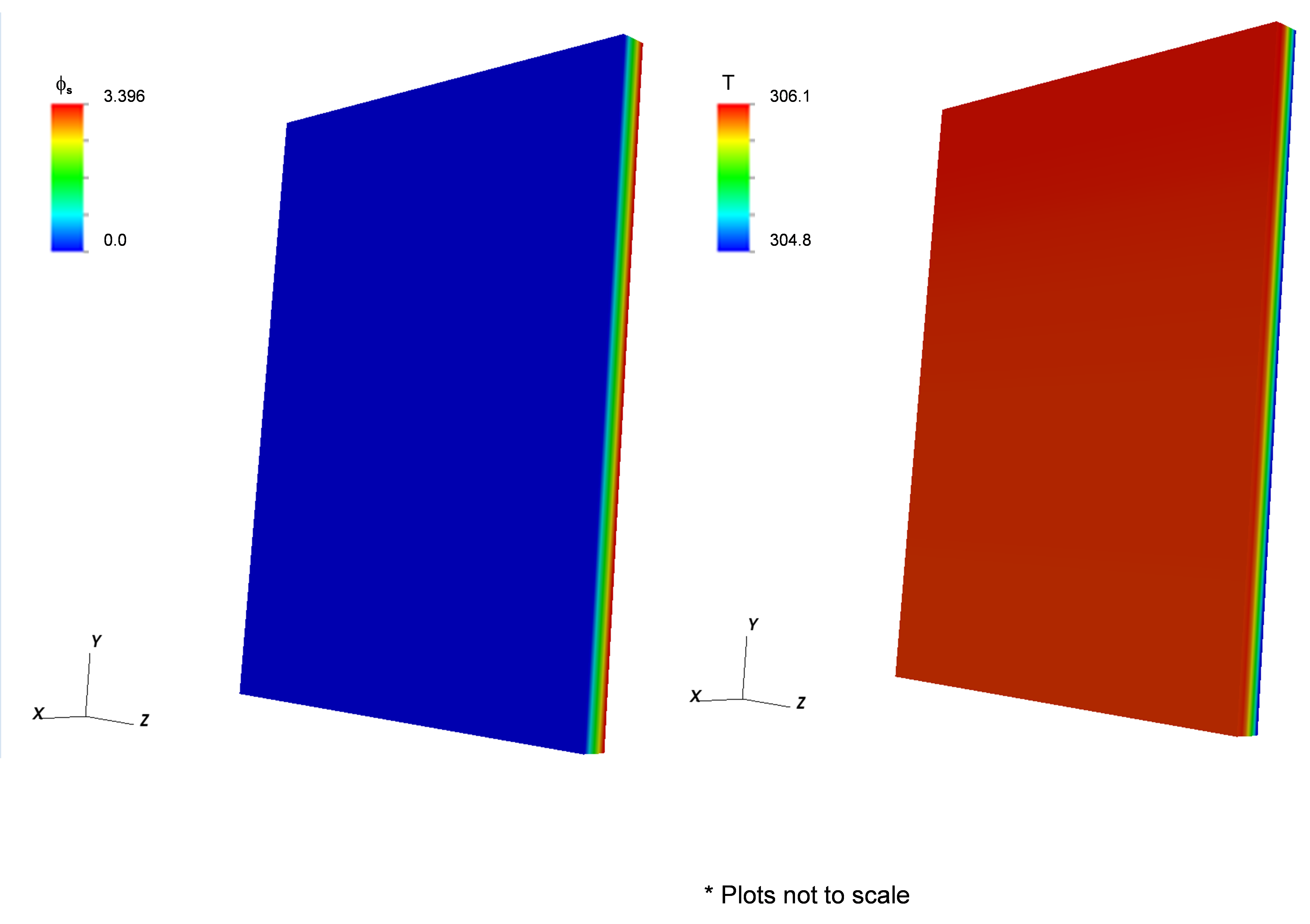
This example (located in the VIBE repository at trunk/examples/case4/) contains the same battery components as example 3 with geometry of a prismatic pouch cell. The electrochemistry is modeled using the NTG model instead of the DualFoil model. Two different cases were simulated, one with one and the other with ten layers in the pouch cell. The model properties are provided below. The corresponding battery state is schematically given in Fig. 7. Typical results for the single layer and ten layer cases are shown in Fig. 8 and Fig. 9, respectively. As expected, the peak temperature increases with the number of layers and the highest temperature is at the core of the cell.
| Physical Properties | Units | Total | Carbon Electrode (Anode) | Lithium Electrode (Cathode) | Al Foil | Cu Foil | Separator |
|---|---|---|---|---|---|---|---|
| Density | kg/m3 | 2500 | 1500 | 2700 | 8960 | 1200 | |
| Heat Capacity | J/Kg-K | 700 | 700 | 900 | 385 | 700 | |
| Thermal Conductivity | W/m-K | 0.01 | 0.01 | 238 | 398 | 0.01 | |
| Electrical Conductance | S/m | 0.001449 | 0.001449 | 383x105 | 633x105 | 0.001449 | |
| (rCp) avg | J/m3-K | 175x104 | |||||
| Height | m | 0.192 | |||||
| Width | m | 0.145 | |||||
| Thickness | m |
1.7x10⁻³ (10 layers) |
|||||
| Current Density | A/m2 | 35 | |||||
| Convective Heat Transfer Coefficient | W/m2-K | 25 |

Figure 7: Battery state file for example 4.
Example 4a: Single layer of a pouch cell (Electrochemical/Electrical/Thermal)

Figure 8: Sample results for Example 4a that shows the electrical potential (left) and temperature (right).
Example 4b: Multiple layers of a pouch cell (Electrochemical-Electrical-Thermal)

Figure 9: Sample results for Example 4a that shows the electrical potential (left) and temperature (right).