Spotweld Models for Advanced High Strength Steels
Development of SWE
One of the objectives of our research project was to develop and demonstrate an FEM model that would improve on the current modeling techniques for the mechanical response of spot welds in structural problems. Because the spot weld model is to be a part of larger, component-level simulations, its computational performance is very important. While detailed FEM simulations of spot weld mechanics with fine spatial discretization yield accurate results, such strategies cannot be afforded at the structural component scale. Impact simulations based on explicit time integration have to obey stable time increment that is proportional to the smallest characteristic spatial dimension in a computational model. Therefore, the smaller is an element size, the larger is the computational effort required to see the computational simulation to an end. In the current vehicle models with typical shell element span of about 5 mm, deformable spot weld elements have size of the order of plate thickness, and are commonly the candidates for the smallest, controlling time increment. For steel sheet thickness of 1 mm and the steel's characteristic speed of sound of 5100 m/s, the stable time increment is equal to the time that a disturbance (stress wave) traverses a finite element, which is about 0.2 microseconds. This time increment is five times smaller than the current target time step of 1 microsecond. The and deformable spot weld element formulations that are currently in use usually increase the stable increment to this target by mass scaling.
Simplified schemes of two spot weld model configurations used in our study are shown in the figure below. The two schemes depict the cross-section of the spot weld joint, where solid and shell element regions represent the spot weld nugget and sheet metal plates, respectively. The standard 4-node shell element has displacements and rotations of the mid-plane as the degrees of freedom (DOF) of its nodes, whereas, layered solid elements and solid shells have only nodal displacements as their DOF. Coupling of the two element types (Model 1) with different types and numbers of DOF is done by constraining DOF of the shell and (shell) solid nodes such that the rotations and displacements of the mid-plane shell nodes are compatible with the displacements of the layered solid element nodes. From accuracy standpoint, the preferred shell element formulation in LS-DYNA for spot weld simulations is assumed strain, selectively reduced (S/R) shell element. Computational effort is tripled compared to standard under-integrated shell elements, but this tradeoff has now been generally accepted for practical simulations because of the improved accuracy and computational stability. Laminate shell theory can be used to relax usual assumption of uniform shear strain through the thickness of the shell to improve approximations of shear distribution close to the nugget, and will be explored further. Through thickness changes of the 4-node shell element can be coupled to layered solid elements, as well. The second formulation (Model 2) uses combination with 8-node solid shell elements to provide better estimate of through-thickness fields in the HAZ area adjacent to the nugget, but additional concerns of thickness and curvature locking need to be taken into consideration. The DOF of solid and solid-shell elements are fully compatible, so that the constraint equations are not confining the stress and strain states as in Model 1. The coupling equations are thereby translated away from the spot weld nugget and are imposed to 4-node shell to 8-node solid-shell connection (Model 2).
LS-DYNA Implementation
The target milestone of the research project was to demonstrate feasibility of the proposed spot weld modeling approach and, if successful, further develop the method into a self-contained FEM formulation in Phase 2. The schematics based on the above constraint conditions of the spot weld assembly with the possible failure zones is shown in figure below.
Stress and strain in possible spot weld failure regions or adjacent elements regions can be used to evaluate various fracture/failure criteria that would initiate failure of the joint. In the current research, a simple failure criterion based on the equivalent strain energy to failure was used. The material properties in the weld region were based on the hardness measurements and process modeling simulations. Yield stresses and hardening curves in spot weld zones are estimated by the yield stress of base material multiplied by the ratio of the hardness values in considered zone and hardness of the base material. Equivalent strain to failure was reduced accordingly to maintain the same strain energy to failure as the base metal. Failure strain trends reported in the literature for various steels show high degree of variability with respect to process conditions, especially for new automotive steels. The above constitutes very simplistic model that will need to be replaced by a more accurate models and criteria in the future, but it was sufficient to illustrate the benefits of the proposed approach. Current version of LS-DYNA does not allow for nodes to be in different constraint sets. In figure below, the node of layered solid element at the juncture of top and bottom plates would have to be in two different constraint sets for each plate. Therefore, it was necessary to insert an extra solid element between the top and bottom layered solid elements to avoid this conflict. The actual constraint is currently under impelmentation in the public domain version of DYNA3D.
Simulations
Lap Shear Specimen Simulations
The standard lap shear specimen geometry was simulated with different FEM resolutions. Specimen modeled with very fine FEM discretization is shown in the figure below. The clamped regions are cut off in the model and replaced by the clamped boundary conditions on the nodes emerging from the clamps. As such, the model does account for any grip slipping and is expected to exhibit stiffer response than experiments.
The simulation results with the coarse FEM mesh are shown below. The figure shows the simulation side view of the spot weld region of the lap shear test with small nugget diameter, and the coarse FEM mesh. The figure shows configurations before and after the failure. The failure of the spot weld in simulation and experiments was along the interface between the two connected sheets. Comparison of the force-displacement data from simulation and the quasi-static test is shown below. The failure of the spot weld in simulation and experiments was along the interface between the two connected sheets.
The resulting force comparison is very close given the experimental scatter and the simplicity of the failure model. Simulation for large spot weld diameter in lap shear test is shown below. The simulation is again reasonably close to the experimentally measured force and stiffness of the assembly.
The spot weld model accurately recovers geometry effect based on intrinsic material properties and a very simple failure condition, without a need for accounting of any extrinsic joint properties such as nugget diameter. Simulations with a rigid nugget core (Model 1R) yielded essentially the same results.
Cross-Tension Specimen Simulations
FEM model geometry configuration with fine mesh discretization for the cross-tension test is shown below. The plate material in the specimen's clamped regions is omitted as for the lap shear mode, and the clamped boundary conditions are imposed on the nodes emerging from the fixture.
Simulation of the cross-tension test of DP780 steel with large nugget diameter (D=5.9mm) is shown below.
The simulated force-displacement data compared with quasi-static experiments is shown below.
The simulation is considerably stiffer than the experiment. When the model is compared with impact experiments, a relatively large scatter of the results can be noted.
The origin of this disparity may be in incomplete clamping in experiments, as the post-test specimen analysis showed traces of slipping in the clamps. The origin of stiffer behavior may be attributed to the size of the shell elements in the HAZ1 zone. The elements in that zone are responsible for the overall failure. The actual failure zone is very small and localizes into a ring of elements in the HAZ1 zone. In the current model, a remedy would be to scale the plastic strain to failure with respect to the size of the finite elements in order to conserve the energy to failure. Strain scaling in strain softening regime and viscous regularization based on strain rate effects, can be employed for this purpose. Finer mesh discretization coupled with more rigorous constitutive models for modeling of localization can be used, as well, although reducing the practicality for large scale structural simulation. Overall, maximum force in the simulation corresponds very well to the tests.
Mixed Mode Specimen Simulations
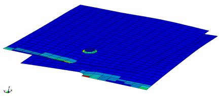
Mixed-mode specimen FEM model for fine mesh discretization is shown in the figure below. The tab regions that are clamped into the fixture are replaced by the clamped boundary conditions on the edge nodes and displacements in the direction of loading. The implemented boundary conditions, therefore, assume perfectly rigid loading mode with no possibility of rotation of the perforated plate component.
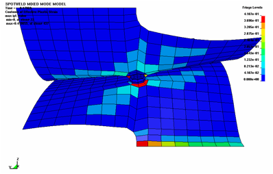
The model is again made structurally stiffer compared to experiments by perfectly clamped and non-rotating boundary conditions. The simulations of 0 degree loading angle resulted in interfacial failure, which was in agreement with experiments. The front view of the simulated specimen geometry at failure is shown below. Colors denote equivalent plastic strain in elements.
The comparison of the force-displacement from a simulation and the tests for the 0 degree loading shows that the simulations are much stiffer. However, the maximum force from simulations again agrees relatively well to experiments.
Simulations of 30 degree loading have shown similar trends as the 0 degree tests. The geometry configuration at (interfacial) failure is shown below.
All the experiments except one exhibited interfacial failure that was also predicted by the simulation. The experimental scatter of the data was very large as is demonstrated below.
Finally, the deformation of the simulated test at 90 degrees loading is shown in Figure 50. The predicted failure mode is pullout as it was observed in all the tests except in one sample.
Simulation results are compared with quasi-static tests in Figure 51. The results from dynamics test had enormous scatter and oscillations that made then unusable. In this case, the stiffness and the maximum force are relatively close. As mentioned above, the considerable variations in the experimental results require further development of test instrumentation, clamping, equipment and loading control in order to generate data for full model verification.


